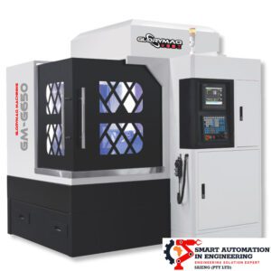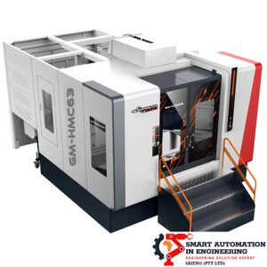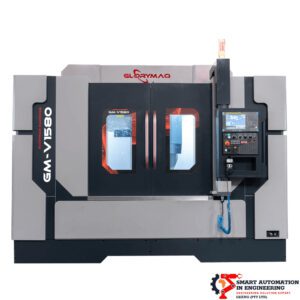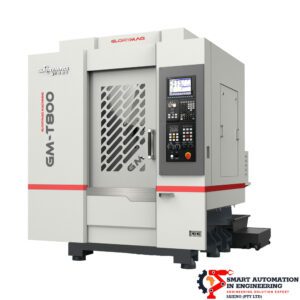
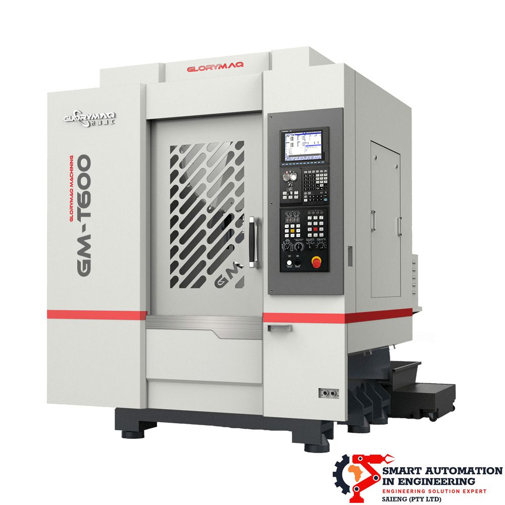
GM-T600 Drilling and tapping machine

The CNC drilling and tapping machine center features a six-point support base structure, enhancing rigidity and vibration resistance to maintain optimal stability during machining operations. Its high-speed servo tool changer ensures fast and reliable tool changes, significantly reducing tool change time and minimizing non-processing delays for improved efficiency.

Need more info?

Share

Mechanical Characteristics of CNC Drilling and Tapping Machine Center

The CNC drilling and tapping machine center is designed for high rigidity, efficiency, and precision, ensuring superior stability and optimized machining performance.

Structural & Performance Enhancements

  • Six-point support base, improving rigidity and vibration resistance for stable operation.
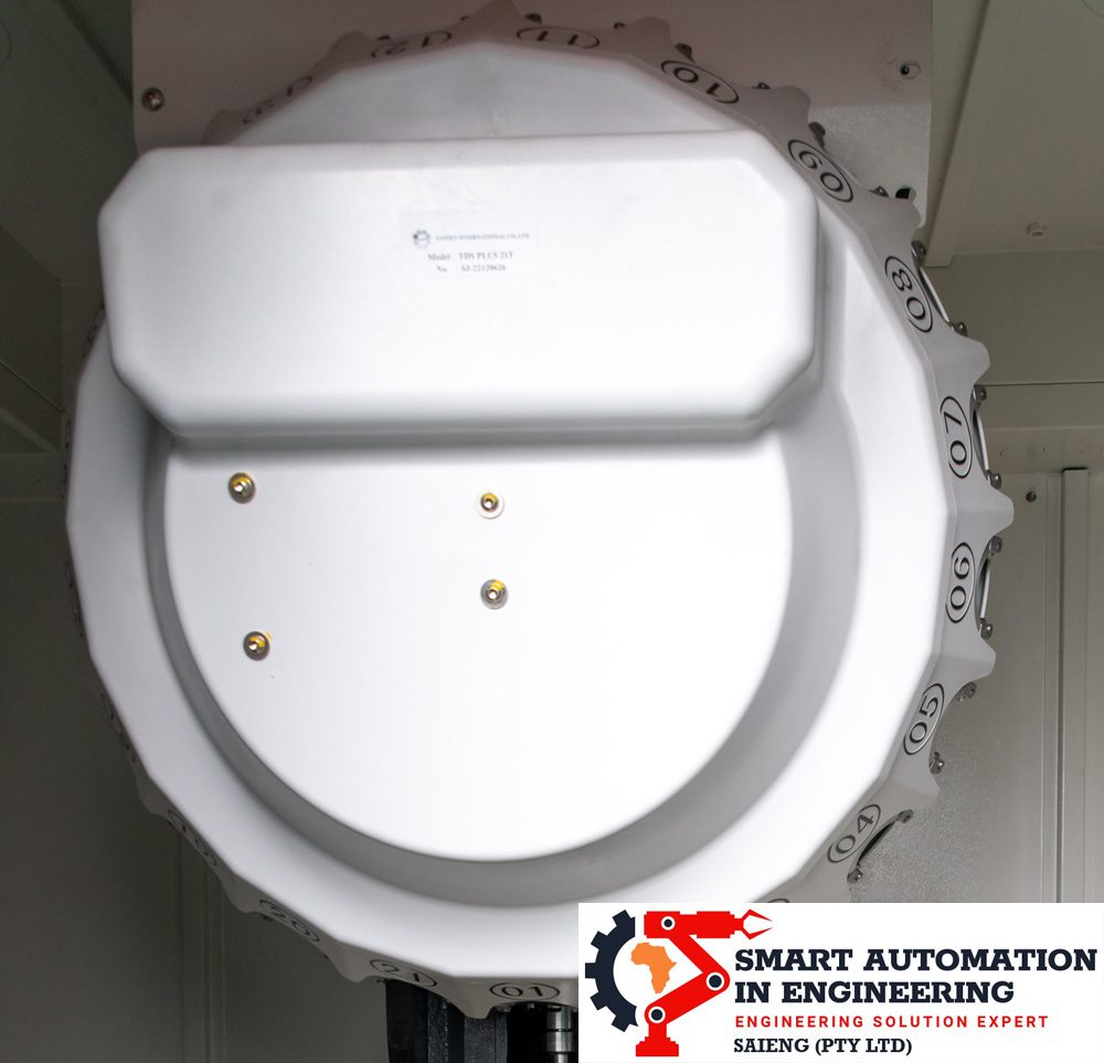
  • High-speed servo tool changer, enabling quick and stable tool changes, reducing non-processing time.
  • Fully enclosed shield design, incorporating backwashing and complete chip removal functions for enhanced reliability.
  • High-speed and high-rigidity tapping, ensuring precision for demanding machining tasks.
  • Clamping arm tool library, facilitating fast and accurate tool replacements, ideal for small-diameter drilling.

Key Advantages

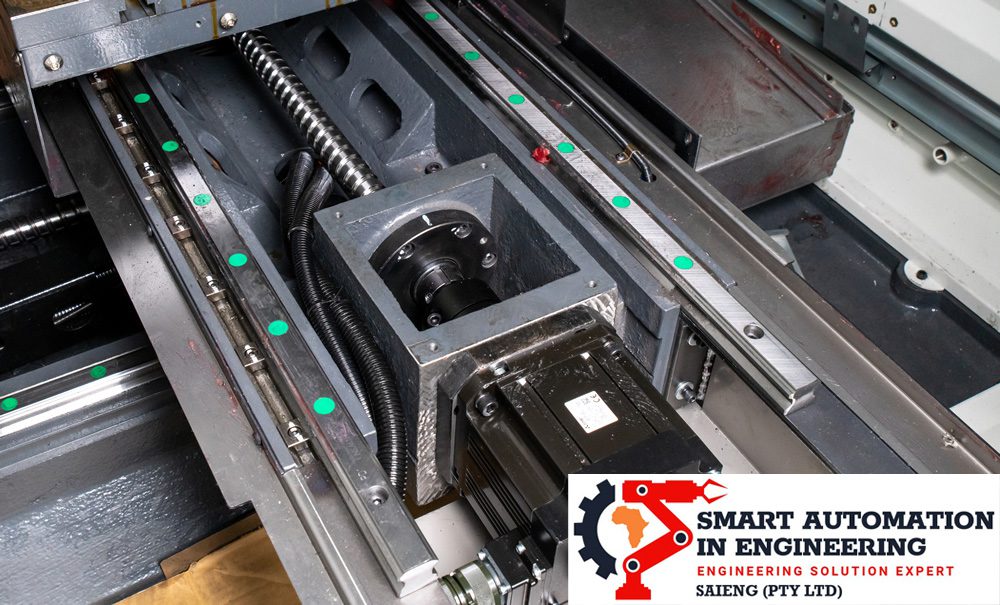
  1. Exceptional rigidity, supported by a rigid bracing structure.
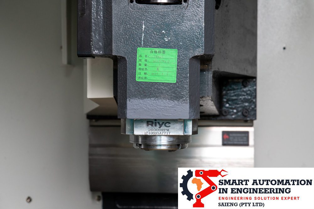
  2. Optimized efficiency, enabled by a direct spindle transmission system.
  3. Space-saving design, reducing machine footprint while maintaining high functionality.
  4. Long-term precision, maintained through specialized heat treatments and six-point displacement support.
  5. Enhanced tool replacement speed, improving production reliability and workflow efficiency.
  6. Fully enclosed protective cover, ensuring effective backwash and chip removal.

Scope of Application

Designed for precision machining, the machine is ideal for processing:

  • Precision parts
  • Mobile phone components
  • 3C products

Product Specifications

Technical Specification

Model

GM-T650

GM-T540

GM-T600

GM-T700

GM-T800

GM-T1000

Axis Travel

X,Y,Z axes

mm

600*450*300

500*400*300

600*400*300

700*450*300

800*500*330

1100*500*330

Distance from spindle nose to worktable

mm

150-450

150-450

150-450

150-450

150-480

150-480

Table

Table size

mm

800*420

650*400

700*420

800*420

1000*500

1100*500

T-slot

mm

14T*3*125

14T*3*125

14T*3*125

14T*3*125

18T*5*100

18T*5*100

Max. table load capacity

kg

250

250

250

250

350

350

Coupling

Spindle taper hole

BT

BT30

BT30

BT30

BT30

BT30

BT30

Speed

rpm

20000

20000

20000

20000

20000

20000

Spindle motor power

kw

5.5

5.5

5.5

5.5

5.5

5.5

Spindle connection mode

Direct drive

Three-axis connection mode

Direct drive

Three-axis motor power

kw

1.5/1.5/3

1.5/1.5/3

1.5/1.5/3

1.5/1.5/3

2/2/3

2/2/3

Transmission mode

Direct drive

Direct drive

Direct drive

Direct drive

Direct drive

Direct drive

Linear guide and ball screw (PMI/HIWIN/HSK)

Linear guide (X/Y/Z)

mm

30

30

30

30

35

35

Ball screw

mm

28*16/28*16/32*16

28*16/28*16/32*16

28*16/28*16/32*16

28*16/28*16/32*16

32*16

32*16

Rapid traverse (X / Y / Z)

)

m/min

36

48

48

36

48

36

Accuracy

Positioning accuracy

0.005/300

Repeated positioning accuracy

0.003/300

Automatic Tooling Changing System

Automatic tool change type

Arm-type/servo tool

Tool Capacity

un

21

Max tool weight

kg

8

Max tool length

mm

200

Maximum tool diameter (Full tool/adjacent empty tool)

mm

160

Tool magazine type

21T

Optional*

System

SIEMENS-828D/MITSUBISHI-M80B/FANUC Oi-MF Plus

4 axis

Optional*

Automatic tool measurement

Optional*

Other

Size

mm

1900*2100*2300

1600*1800*2250

1800*2000*2300

2100*2200*2350

2300*2320*2350

2500*2320*2350

Evaluated machine weight including accessories

kg

3500

3100

3300

4100

3900

4100

Scroll to Top