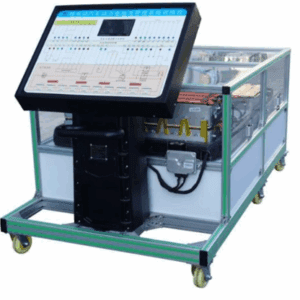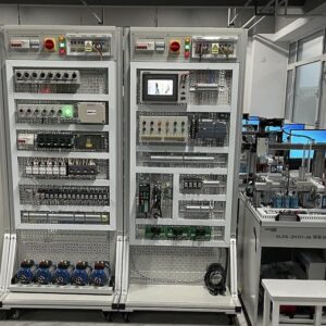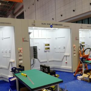
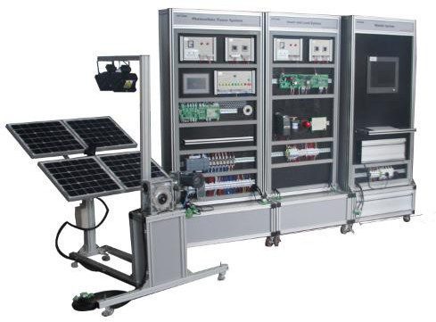
SAI-GF05 Solar power generation training system consists of a photovoltaic power system, photovoltaic power supply system, the inverter and the load system, monitoring system components. SAI-GF05 solar power generation training system uses modular structure, each devices and systems have independent functions, compose solar composition generation training system.
Product Specifications
Equipment features
1. This system adopt three-dimensional structure and standard patchboard, experiment modular exposed completely, strong presence, makes learners into learning roles quickly, complete closed-loop control mode allows users to operate it more humane.
2. The wind-photovoltaic complementary training system adopt ARM control system,a high-performance control type,can full-intelligent control the battery charging&discharge and draught fan brake.
3. Off-grid inverter module boot the front end of an 8-bit MCU driving control, front and rear axles output MOS FET imported to make more stable performance. We can provide a stable learning process 220V pure sine wave AC power.
4. Wind-photovoltaic complementary training system can make student move and dismount this device by themselves, easy to use, No noise no pollution.
Equipment parameter
Dimensions:
Photovoltaic power unit
1610×1010×1550mm Training cabinet
3200×650×2000mm
Module Introduction.
1. Photovoltaic power unit
a)Composition
Photovoltaic power supply equipment is mainly composed of the photovoltaic battery components, delineascope, light sensor, light sensor control box, horizontal direction and pitching direction mechanism, pendulum lever, pendulum lever reduction box, pendulum rod support, single phase AC motor, capacitor, DC motor, proximity switch, micro switch, base support equipment and parts, as figure 1 shows.
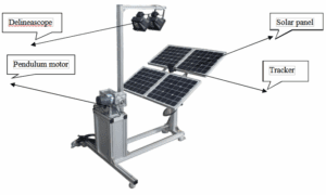
Figure 1 Power Supply for Photovoltaic.
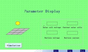
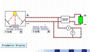
Touch Screen Display Interface
Photovoltaic battery square array is composed of 4 multipled photovoltaic battery components, light sensor install in the center of battery square array.2 300W delineascopes install on pendulum bracket, bottom of pendulum connect to the output of reduction box, input of reduction box connect to the single phase DC motor. When machine rotating, delineascope achieve circular motion actuated by reduction box. Pontes between bottom of delineascope and pedestal bracket installed proximity and micro switch, be used to the limit and protection of delineascope location. Horizontal direction and pitching direction mechanism is composed of horizontal movement reduction box, pitching motion reduction, DC motor, proximity & micro switch. When DC motor rotating, horizontal movement reduction box actuate photovoltaic battery square array eastward-moving or westward-moving horizontally, pitching motion reduction actuate photovoltaic battery square array pitch northward-moving or southward-moving, proximity and micro switch are used to the photovoltaic battery square array’s limit and protection.
Photovoltaic battery component
Rated power: 20W
Rated voltage: 17.2V
Rate current: 1.17A
Open-circuit voltage: 21.4V
Short-circuit current: 1.27A
Dimension: 430mm × 430mm × 28mm
Photovoltaic power supply system

Composition
Solar photovoltaic power supply system consists of a control unit, the PV output display unit, touch screens, photovoltaic power supply control unit, ARM control unit, the interface unit, Siemens S7-1200PLC, relay group, terminal block, battery, adjustable resistors, circuit breakers, 12V switching power supply, mesh frame and other components.
Control ways
Chase sun function of photovoltaic power supply control unit include 2 state manual control box and automatic control, can manual or automatic operate the 2 axis tracking, light condition, light movement.
Control unit and interface unit.
Battery charging process and charging protection is completed by DSP control unit, interface unit and the process, the battery discharge protection is completed by DSP control unit, interface unit and relay, when the battery discharge voltage is lower than rated value, ARM control unit output signal actuate relay to work , relay normally -closed contact break, cut off the battery discharge circuit.
Storage Battery
Battery choose section 4 control valve sealed lead acid battery, the main parameters Capacity 12V 18Ah/20HR
Weight 1.9kg
Dimension 345mm×195mm×20mm
Inverter and load system
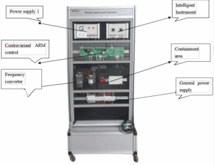
Composition
Inverter and load system mainly consists of inverter power control unit, inverter output display unit, inverter, inverter parameter detection module, frequency converter, three-phase ac motor, luminous tube stage lighting module, caution light, wiring the row, the circuit breaker, mesh frame, etc.
Input of inverter provided by photovoltaic power generation system, wind driven generator or generator, inverter output single 220V 50HZ AC power supply. AC governor system is composed of frequency converter and 3 phase AC motor, inverter output AC 220V power supply, that is the input power supply of frequency converter, frequency converter switch single phase 220V into 3 phase 220V for 3 phase 220V AD motor use. The inverter power supply control unit’s AC 220 power supply provided by inverter, inverter power supply control unit output DC24V,it be used for luminescent tube stage lighting module. Inverter test module is use to test inverter’s dead
zone, fundamental wave, SPWM waveform.
Inverter
Inverter is a device to be use to switch low tension DC power supply into high tension AC power supply, it has many different kinds, each operation principle and operation process is different. This inverter is composed of DC – DC booster PWM control chip unit, drive + booster power MOS pipe unit, step-up transformer, SPWM chip unit, high voltage driver chip unit, full bridge inverter power MOS pipe unit, LC filter.
Monitoring system
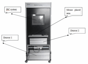
Composition
Monitor and control system is mainly composed of multifunction, keyboard, mouse, the wiring row, the power supply socket, communication line, Microsoft operating system software, force control configuration software component.
Monitor and control system function
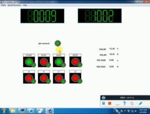
Configuration interface make and display
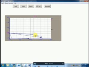
Draw of Volt-ampere curve, frequency curve
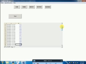
Statement date store, print
Communication
Monitoring system communicate with controller, PLC, instrument.
Interface
1. Monitoring system has the main interface, photovoltaic power supply system interface, wind power supply system interface, inverter and load system interface, scenery complementary energy conversion interface, respectively show their running state parameters.
2. Photovoltaic power supply system interface setting corresponding button, realize photovoltaic battery phalanx automatic tracking.
3. Wind power supply system interface Settings corresponding button, realize wind generator side wind yaw control.
4. Has the photovoltaic power generation acquisition statements and wind power generation set statements, record photovoltaic output voltage, current, wind generator output voltage, current, Inverter and load system inverter output voltage, current, power, etc. data and print data report.
RFID intelligent power transmission module
It is required to be used for the overall power control and management of the equipment, high-frequency RFID, the working frequency is 13.56MHz, and the power management is performed by swiping the card through the RFID RS485 communication method, and there will be corresponding prompt sounds and LED indicators.
In addition to power management by swiping cards through RS485 communication, RFID itself also has the following functions:
1. OLED liquid crystal display card reading information. The card number and data of the RFID card and the error command are displayed by default, and the actual information to be displayed can also be set through the software, and the cause of the error can be quickly located according to the error command.
2. RFID will have corresponding sound prompts in different states, and users can judge the current state of the RFID reader according to the prompt sound.
3. data verification. RFID write data can be verified in two ways:
3.1. Compare the consistency of written data and read data through the OLED display screen; (at least two physical pictures should be shown in the bidding documents)
3.2. Judging by the verification command
3.3. Parameter setting and function test. The parameter setting and reading and writing function test of the device can be carried out through the built-in software.
4. the communication method. The RFID reader supports the ISO-15693 protocol and provides two standard communication protocols, ModBus_TCP or ModBus_RTU.
Main experiment training contents
| 1,Photovoltaic power supply equipment | |||
| Serial | Name | Technical Parameter | Quantity |
| number | |||
| 1 | Battery Component | Power:20W Error:±5%
Output Voltage:17.2V OutputElectriccurrent:1.17A Open Circuit voltage:21.4V Short circuit voltage:1.27A Work environment Temperature:45℃±2℃ Size:430×430×28mm |
4 |
| 2 | Chasesun sensor | Output voltage:0-5V
Trackingprecision:1degree Construction:4 bridge |
1 |
| 3 | Delineascope | Wingarm:Turbineworm(2reducercasing) Voltage:220V
Frequency:50Hz Electricity:1.36A Max frequency:300W |
2 |
| 4 | Chase sun organization | Construction:Turbineworm(reducercasing) Drive:DC motor
Axis Number:double axis two-dimension |
1 |
| 2,Photovoltaic power supply equipment | |||
| Serial
number |
Name | Technical Parameter | Quantity |
| 1 | Powercontrol
unit |
Earthleakageprotectioncircuitbreaker,AC220Vand
DC24V status indicator, power socket |
1 |
| 2 | Photovoltaic control power
unit |
Earthleakageprotectioncircuitbreaker,AC220Vand DC24V status indicators | 1 |
| 3 | functional
module |
ARM core board, communication control board,
photovoltaic power main board |
1 |
|
4 |
DC input unit | Ammeter: DC 0-5A | 1 |
|
5 |
Photovoltaic power supply
control unit |
Battery board tracking direction: East, South, West, North | 1 |
|
6 |
PLC | S7-1200 1214C AC/DC/RELAY | 1 |
|
7 |
touch screen | 7 inch color | 1 |
|
8 |
Expansion | DI 8x24VDC/DQ 8xRelay_1 | 1 |
|
9 |
Adjustable
resistance |
Range: 0-1000 Ω, steplessly adjustable (with scale) | 1 |
| 3,Inverter and load system | |||
| Serial
number |
Name | Technical parameters | Quantity |
| 1 | Inverteroutput display
module |
Ampere meter:AC 0-5A Voltage Meter:AC 0-500V
interface:RS485 |
1 |
| 2 | Inverterpower
supplycontrol module |
Includeearthleakagecircuitbreaker,AC220Vand DC24V condition indicator light | 1 |
| 3 | Inverter | InputVoltage:DC12V
Input voltage range:DC9.5V-15.5V Output voltage:AC220V±5% Rated output ampere:1.4A Output frequency:50Hz±0.5Hz Rated frequency:300VA Output waveform:sine wave waveform distortion:<5% Transform frequency:>85% Experiment module:sine wave inverter principle module |
1 |
| 4 | Switchpower
supply |
model:DR-120-24
inputvoltage:AC220V |
1 |
| outputvoltage:DC24V
outputampere:5A |
|||
| 5 | Inverter | siemensV20-0.37Kw | 1 |
| 6 | Motorloading | Frequency:40W Voltage:AC220V
Rotatingspeed:1350rpm |
1 |
| 7 | Lightloading | 1 | |
| 8 | valvecontrol sealed
lead-acid battery |
Volume 12V 18Ah/20HR Weight 1.9kg
size 345mm×195mm×20mm |
4 |
| 4、monitor system | |||
| No. | Item | Specs | Qty |
| 1 | Industrial
computer |
6serialportswithkeyboardandmouse | 1 |
| 2 | Configuration
Software |
Chinese | 1 |
| 5.Test bench | |||
| No. | Item | Specs | Qty |
| 1 | Mesh plate test bench | Verticalmeshplatebasicstructure:belowthetoolbox+4 wheels, above the vertical mesh plate
Size: 800 (length) × 600 (width × 2000 (height) Externalframecomposition:aluminumalloyprofiles; Inline sprayed steel plate Steel plate size: 1200mm × 820mm Steelplatethickness:2mmmeshplatewithpush-pull drawer, drawer with profile frame, 2mm steel plate bottom; The bottom of the mesh frame is equipped with pulleys. |
4 |
| 2 | Microsoft operating system
software |
Window7 | 1 |
| 3 | Communication
Cable |
1 | |
| 4 | Experimental | Photovoltaicpowersystemtrainingguide | 1 |
Supporting tools, supplies
| Serial
number |
Name | Technical Parameters | Quantity |
| 1 | Multimeter
(Uni) |
Multimeter (Uni) | 1 |
| 2 | Pinterminal
crimping tools |
1 | |
| 3 | Forkterminal
crimping tools |
1 | |
| 4 | Smallflathead
screwdriver |
2.4*40 | 1 |
| 5 | SmallPhillips
screwdriver |
2.4*40 | 1 |
| 6 | Long-handled
screwdriver |
PH1*150 | 1 |
| 7 | Strippers | 0.2-1.2m㎡ | 1 |
| 8 | scissors | Shortmouthsmallscissors | 1 |
| 9 | Needle-nose
pliers |
6-150 | 1 |
| 10 | Diagonal
pliers |
6-150 | 1 |
| 11 | tweezers | 1 | |
| 12 | Electriciron | 60W Adjustable | 1 |
| 13 | Super-plastic
toolbox |
17〃 | 1 |
| 14 | charger | 12V | 1 |
| 15 | Wire (red) | BVR-2.5m㎡ | 50m |
| 16 | Wire (red) | BVR-0.75m㎡ | 100m |
| 17 | Wire (red) | BVR-0.3m㎡ | 100m |
| 18 | Wire (black) | BVR-2.5m㎡ | 50m |
| 19 | Wire (white) | BVR-0.3m㎡ | 100m |
| 20 | Wire (blue) | BVR-0.3m㎡ | 300m |
| 21 | Crimps | Forkedtype:¢1.25-3100/pack | 3 |
| 22 | Crimps | tubetype0.51000/pack | 1 |
| 23 | Crimps | tubetype2.5 | 100 |
| 24 | Solderwire | ¢0.8 | 1 |
Commissioning tool
|
1 |
Installation and commissioning tool |
Handheld Digital Oscilloscope, |
UTD1025 C |
1 |
Set |
Uni-t |
Training content
1. Working Principle Experiments of Single Crystal Silicon Photovoltaic Cells
2. Design experiment of solar cell module square array
3. Composition and control experiment of photovoltaic power supply device
4. PLC Programming Manual and Automatic Photovoltaic Cell Tracking Solar Experiment
5. Operating Characteristic Experiments of Photoresistors and Voltage Comparators
6. Operating Principle Experiments of Light Sensors
7. Design of Electrical Control Principle for Photovoltaic Power Supply System
8. I-U Characteristic Test of Photovoltaic Cells
9. Experiments on output power characteristics of photovoltaic cells
10. Experiments on PWM Charging Process of Battery by Controller
11. Discharge Protection of Battery by Controller
12. Actual Charging Test of Batteries
13. Simulated charging experiment of storage battery
14. Working Principle Experiment of Inverter
15. Design and Connection Experiments of Inverters with Different Loads
16. Communication mode and connection experiment between PC and each unit
17. Communication Protocol Setting Experiments
18. Application experiment of configuration software
19. Basic Development Process Experiments of Configuration Software
Related products
-
 CNC Training Equipment
AIQC-EVBMS Battery Management System (BMS)
-
CNC Training Equipment
SAI-H101 Intelligent electrician comprehensive training and assessment equipment
-
CNC Training Equipment
SAI-102 Internet of Things Basic Training Station
-
CNC Training Equipment
SAI-1214F electrical device training system